Last year a laser scan of part of the mountain side, to establish a base line. So this year we have performed a second laser scan to compare to the first one. This data will be analysed later to discover how the rock face has moved in the last year.

Last year a laser scan of part of the mountain side, to establish a base line. So this year we have performed a second laser scan to compare to the first one. This data will be analysed later to discover how the rock face has moved in the last year.
When we visited the estate in June we left a camera deployed to take pictures of any wildlife that went past. The camera deployed was an off the shelf trail camera to give us an idea of what we could expect to capture if we developed our own imaging system. Below is one of the pictures taken by the system.
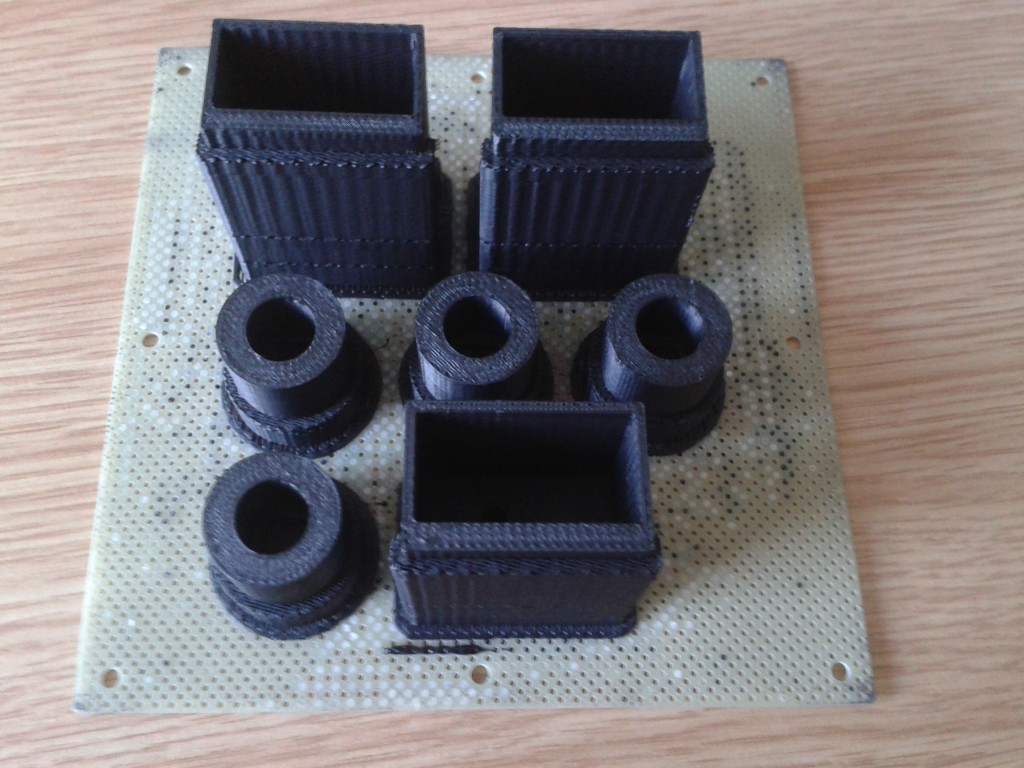
For this project we are creating custom 3D printed parts for the sensors. The two parts we are creating are housings for pressure sensors. One is to be submerged in a river, the other is to measure atmospheric pressure.

This is how the parts appear when first removed from the printer. There support material to make sure the parts don’t fall over or droop during printing
This project has required the design and development of several custom sensors. This is the first one to have been built. It uses 5 one-wire temperature sensors attached to an AVR. The AVR then runs code to interface with the sensors. In order to connect to the main sensor node the AVR uses RS-485. This means that it can be away from the main node, and because of the multi-drop nature of RS-485 multiple such devices could be attached. The other sensor nodes also interface using RS-485 so each node could have different types of remote sensor attached.
The first batch of PCBs to be used in the project have been created. These boards will take a 12V input and give a 5V 2A output. These will be useful for powering devices in the first tests that are carried out. There are a few more boards on the way including 5V 250mA boards, which will also be used for testing and powering external peripherals.